-
 Publications
-
 Research activities
-
Hybrid mobile hydraulics for excavators
-
Lubricating Systems with Rotating Shafts
-
0D models of axial piston pumps/motors
-
CFD studies on conical poppet valves
-
CFD analysis of gerotor pumps
-
Lumped parameter models of crescent pumps
-
Lumped parameter models of vane pumps
-
Lumped parameter models of gerotor pumps
-
Coupled simulation of telehandler hydraulics
-
 Modelling of brake booster vacuum pumps
-
Absorbed energy in ICE lubricating pumps
-
Multi-body simulation of axial piston pumps
-
Development of variable flow lubricating pumps
-
Optimization of ICE lubrication gerotor pumps
-
-
Research projects
Modelling and simulation of brake booster vacuum pumps (2010-2011)
Aim of this work was the development of a lumped parameter simulation model of single-vane vacuum pumps for pneumatically actuated brake boosters. Kinematic and fluid-dynamic models were integrated in a simulation environment to create a tool aimed at evaluating the vacuum pump performance and at guiding the designer during the prototype development. Great emphasis was placed on the evaluation of the geometric quantities of the control volumes into which the vacuum pump was divided. For each control volume the mass and energy conservation equations led to the determination of the instantaneous pressure. The volume of each variable chamber and the respective angular derivative were calculated as function of the shaft position starting from the stator track profile supplied as a generic closed polyline. Flow areas between each chamber and the inlet/outlet volumes during a complete shaft revolution were evaluated directly from a data file containing the x-y coordinates of the passage area contour. Different leakage paths were also considered. Specific attention was dedicated to the simulation of the lubricating fluid throughout the vacuum pump in order to consider possible overpressures due to the presence of a trapped volume of oil, above all during cold starts. To achieve this target the equations describing the behavior of the liquid and gaseous phases were applied simultaneously and the current fraction of oil was evaluated for each variable volume chamber. The model was able to work with an oil fraction ranging from 0% to 100% without introducing discontinuities in the differential equations. Experimental tests have confirmed a good matching with the simulation results in terms of pressure vs. time characteristics and absorbed torque.
The vacuum pump model was implemented in the LMS AMESim environment (currently Simcenter Amesim). However, due to the complexity and peculiarity of the unit under study, many new components (submodels) and functions were developed from scratch in C language. Figure 1 shows the simulation model of the complete system. The core of the vacuum pump, made up of three variable volume chambers, port plate and leakage paths, was simulated through the supercomponent facility. It is provided with three inlet ports (primary “in1” and secondary “in2” users and the hydraulic circuit “oil”) and two outlet ports “out1” connected with the reed valve. The supercomponent also includes the submodels for the evaluation of all geometric quantities. Some CPU consuming operations, such as the evaluation of the flow areas as function of the shaft angle, are executed only once at the first call of the submodels for the chamber 1, after that the interpolated values are used with a proper phase shift.
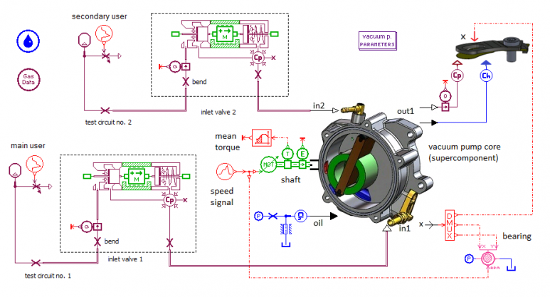 Figure 1
Performance test consists in measuring the pressure in a fixed test volume as function of time once the connection with the atmosphere has been closed. In figure 2 the comparison between the simulated and experimental pressure-time characteristics at 3600 rpm is shown.
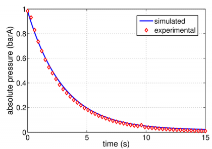 Figure 2
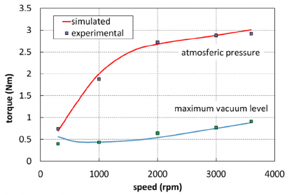
In figure 3 the steady-state absorbed torque is shown as function of the speed at two extreme suction pressure values.
More details are available in:
RUNDO M, SQUARCINI R, 2013: Modelling and Simulation of Brake Booster Vacuum Pumps