-
 Publications
-
 Research activities
-
Hybrid mobile hydraulics for excavators
-
Lubricating Systems with Rotating Shafts
-
0D models of axial piston pumps/motors
-
CFD studies on conical poppet valves
-
CFD analysis of gerotor pumps
-
Lumped parameter models of crescent pumps
-
Lumped parameter models of vane pumps
-
Lumped parameter models of gerotor pumps
-
Coupled simulation of telehandler hydraulics
-
Modelling of brake booster vacuum pumps
-
Absorbed energy in ICE lubricating pumps
-
Multi-body simulation of axial piston pumps
-
 Development of variable flow lubricating pumps
-
Optimization of ICE lubrication gerotor pumps
-
-
Research projects
Development of variable displacement vane pumps for ICE lubrication (2000-2008)
In the development of modern internal combustion engines an increasingly relevant issue is targeted at emission reduction and fuel economy. Variable displacement lubricating oil pumps can make a contribution in this direction owing to their intrinsic capability of matching oil consumers demand at various operating conditions besides the critical situation at hot engine idling.
A thorough study of variable flow pumps has been made in cooperation with Pierburg Pump Technology. Starting from 2000 diverse solutions have been analysed and contrasted by means of accurate simulation models and experimental tests. The first step was an in depth study of an intermediate solution represented by a variable timing gerotor pump. The reduction of the delivered flow, at equal pump speed, was obtained by a partial rotation of the port plate. Figure 1 shows the flow rate as function of the sector rotation in the DCIP configuration (Delayed Closing of Inlet Port).
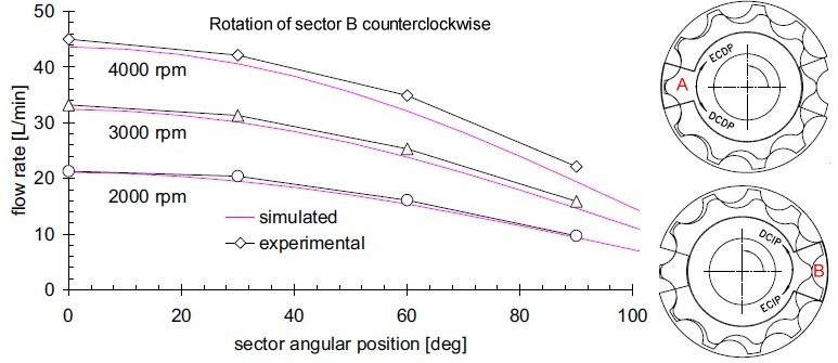 Figure 1
However better results were attained with variable displacement vane pumps. Figure 2 reports the simulated absorbed torque as function of the engine speed at fixed oil temperature: to form a common basis for comparing the three pumps, the control strategies of the variable flow units have been so assessed to give the same flow rate, at given operating conditions, of the fixed displacement unit.
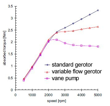 Figure 2
Research activity was also focused on the selection of more suitable displacement controls. In fact a direct acting device is not able to control the pump displacement in all operating conditions. This is ascribed to the growth of the resultant force active on the stator track originated by the incomplete filling of pump chambers. For this reason a piloted control has been conceived, designed and developed. The pump displacement control is carried out by two linear actuators with different front end areas. The smaller (contrasting actuator) is subject to pump delivery pressure, the larger (displacement actuator) is instead acted upon by a controlled pressure originated from delivery pressure. Pressure control is implemented by a remotely piloted two-port valve and a fixed orifice. Figure 3 compares the flow-pressure characteristics simulated with two different controls (markers represent experimental data).
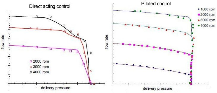 Figure 3
Different types of 2-level pressure setting controls have been analyzed and simulated. In Figure 4a the scheme of an electro-hydraulic systems is presented. The chamber of the displacement actuator can be vented by a two-position ball poppet electro-valve EV controlled in open loop by the engine ECU. For less critical operating conditions, normally medium-low oil temperature and low engine speed, the electro-valve is actuated and the surface area A of the larger actuator is exposed to the inlet pressure. In such a configuration the displacement control is directly operated and the stator eccentricity is reduced when the equivalent pressure setting p1* of the spring acting on the stator is exceeded. For more severe operating conditions, the electro-valve is maintained shut and the displacement control is piloted by the pressure relief valve with cracking pressure p2* greater than p1*. Depending on the lubrication requirements of the specific engine, the second configuration can be used for example when the oil temperature is high or very low or when the engine runs at high speed.
In figure 4b the comparison between the simulated steady-state characteristic and the experimental curves are shown.
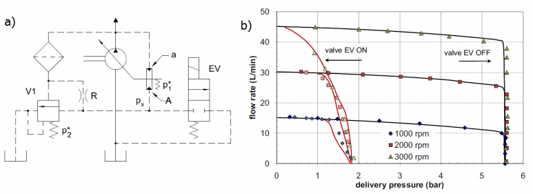 Figure 4
Another example, shown in figure 5a, is able to modify the pressure setting as function of the oil temperature and the current pump displacement. A normally open two-port valve V2 connects the displacement actuator to the suction side of the pump. The valve is operated by a wax thermostatic element that senses the oil temperature. At high temperature, the wax melts and the increment of volume moves a rod that fully closes the valve; in this case, the control works as the system of figure 5a when the electro-valve is closed. Conversely, at low temperature the valve remains open since the wax is solid and does not exert any actuation force. Moreover, the connection between the displacement actuator and the suction side is always closed for low values of the pump eccentricity, since the stator itself works as a variable restrictor VR. In figure 5b the simulated and experimental characteristics are shown at low temperature (V2 open).
The pump begins to reduce the displacement when the lower pressure level p1* is achieved. This value decreases as the angular speed increases due to the growth of the perturbing force acting on the internal track of the stator. However, a very gradual reduction of the eccentricity can be observed due to the progressive closing of the restrictor VR that generates the increment of the pressure px. In the range from about 2.5 to 5.1 bar, the pressure in the displacement actuator is high enough to counterbalance the internal force and the force exerted by the contrasting actuator; in such operating conditions the pump runs at partial and almost constant displacement, between 57% and 67% of the maximum value.
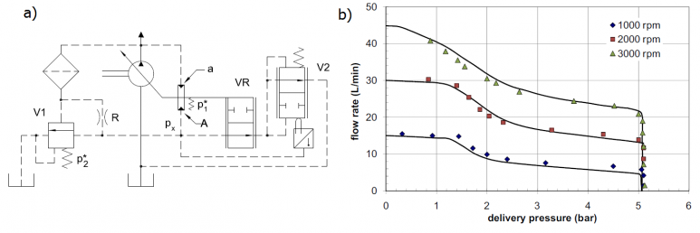 Figure 5
More details are available in:
NERVEGNA N, MANCO' S, RUNDO M, 2001: Variable Flow Internal Gear Pump
MANCO' S, NERVEGNA N, RUNDO M, ARMENIO G, 2004: Displacement vs flow control ...
RUNDO M, SQUARCINI R, 2011: Discrete Pressure Controls in IC Engine Lubricating Pumps