-
 Publications
-
 Research activities
-
Hybrid mobile hydraulics for excavators
-
Lubricating Systems with Rotating Shafts
-
0D models of axial piston pumps/motors
-
CFD studies on conical poppet valves
-
CFD analysis of gerotor pumps
-
Lumped parameter models of crescent pumps
-
Lumped parameter models of vane pumps
-
Lumped parameter models of gerotor pumps
-
 Coupled simulation of telehandler hydraulics
-
Modelling of brake booster vacuum pumps
-
Absorbed energy in ICE lubricating pumps
-
Multi-body simulation of axial piston pumps
-
Development of variable flow lubricating pumps
-
Optimization of ICE lubrication gerotor pumps
-
-
Research projects
Coupled simulation of telehandler forks handling hydraulics (2011-2012)
The simulation model of the forks handling system of a telehandler has been developed. The study has been performed through coupled simulation of two software codes, AMESim (now Simcenter Amesim) for the 1D modelling of hydraulics and Virtual Lab for the mechanical modelling of the telescopic boom and forks. In context the advantage is that coupled simulation involves just one integrator with significant savings in computer time. Aim of the analysis is the development of a validated model capable of predicting system behaviour with adequate accuracy in different operating conditions. Following a kinematic analysis to evidence the characteristics of the mechanical system, such as the automatic forks levelling, forks lever ratio and overrunning load conditions, the detailed hydraulics modelling is discussed with emphasis on overcentre valves. The hydraulic model is interfaced with the mechanical one that based on forces consequent to load induced pressures evaluates in turn velocities and displacements. The complete model received experimental validation through significant boom and forks duty cycles. A fair agreement has been reached confronting experimental and predicted outcomes.
In figure 1 the model in Simcenter Amesim is shown. The system under study is comprehensive of a two-element telescopic boom that bears, through mechanical links and leverages, the forks implement. Two dedicated double acting linear actuators, namely the telescopic boom (TBA) and forks cylinder (FA), respectively allow variation of boom inclination and forks swing. The third movement involves a third actuator that allows the boom extension. Both single and simultaneous commands on boom and forks can be effected. In addition an automatic hydraulic forks levelling system exists through an additional linear actuator (FLA). Accordingly, as boom is lifted or lowered, forks are kept parallel to the ground without operator’s intervention. The figure also shows the Amesim – Virtual Lab interface linked to the three linear actuators TBA, FA and FLA.
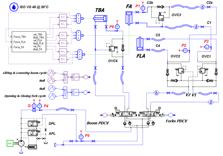 Figure 1
The Virtual Lab model shown in figure 2 was developed by assembling and linking all subassemblies to arrive at a complete virtual description of the boom and forks implement of the telehandler. Care was exercised in the definition of local coordinates reference systems for proper identification of mutual control variables. The end-stop modelling was done within Virtual Lab by means of point-to-point contact elements. Loads acting on the forks are applied within Virtual Lab.
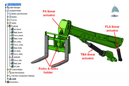 Figure 2
In figure 3 analytical (continuous line) vs. simulated (dash-dot line) delivery pressure signals are contrasted. The work cycle consists in lifting and lowering the telescopic boom with forks parallel to ground. Starting with the boom at rest in a horizontal position and after a short initial delay, a command is issued through the joystick onto the PDCV1 aiming at lifting the boom to its maximum inclination.
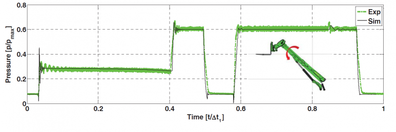 Figure 3
More details are available in: