-
 Publications
-
 Research activities
-
Hybrid mobile hydraulics for excavators
-
Lubricating Systems with Rotating Shafts
-
0D models of axial piston pumps/motors
-
 CFD studies on conical poppet valves
-
CFD analysis of gerotor pumps
-
Lumped parameter models of crescent pumps
-
Lumped parameter models of vane pumps
-
Lumped parameter models of gerotor pumps
-
Coupled simulation of telehandler hydraulics
-
Modelling of brake booster vacuum pumps
-
Absorbed energy in ICE lubricating pumps
-
Multi-body simulation of axial piston pumps
-
Development of variable flow lubricating pumps
-
Optimization of ICE lubrication gerotor pumps
-
-
Research projects
CFD studies on conical poppet valves (2015-2017)
This study deals with the 3D and 0D simulation of a conical poppet pressure relief valve with flow-force compensation.
In hydraulic valves, steady-state performance is strongly affected by flow forces, which are generated by changes in fluid momentum inside the valve. In pressure relief valves, the undesired effect is an increase in regulated pressure as the discharged flow rate rises.
Several techniques exist for compensating flow forces, most of which are applied to spool valves. In conical poppet valves, compensation can be achieved by deflecting the outgoing flow in order to reduce the change in axial momentum. The design difficulty lies in the fact that the jet angle does not coincide with the trailing edge angle of the deflector. Moreover, the force intensity is also a function of the fluid velocity at the jet exit, which depends on the jet spreading. In addition, if the angle tends to 180°, the jet is partially reflected inward by the poppet seat, generating a vortex. Therefore, accurate prediction of valve behavior requires CFD simulation.
A dynamic model of the valve was developed in ANSYS Fluent® and Simerics MP+®, taking into account the interaction between poppet dynamics and the pressure field. Notably, SimericsMP+was applied for the first time in this type of study, with a dedicated subdivision of the fluid domain designed to identify regions with fixed, deformable, and sliding meshes.
The models are able to predict the opening force generated on the deflector by jet deviation and thus the equilibrium position of the poppet as a function of the flow rate, which determines the regulated pressure. The steady-state flow–pressure characteristic of the valve was validated at three different cracking pressures using a dedicated test bench.
Once validated, the CFD codes were used to study the influence of deflector geometry on the opening force. They were also employed to provide input data for a lumped-parameter model of the valve. In conclusion, the 3D transient model proved to be an effective tool in the pre-design stage, as well as a valid substitute for experimental tests when tuning a lumped-parameter model.
Figure 1 shows the pressure field in the valve, with the flow direction from left to right. The locations of the pressure transducers, P1 at the inlet port (P) and P2 at the outlet port (T), are also indicated. An increase in pressure of up to 10 bar is observed on the left surface of the flow deflector, due to the jet impact shown in Figure 2.
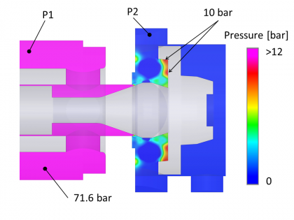 Figure 1
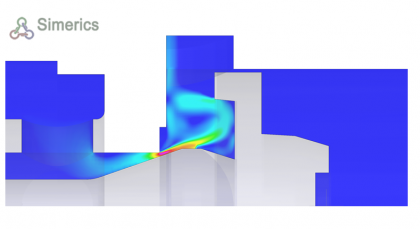 Figure 2
Figure 3 shows the comparison between simulated and experimental steady-state characteristics at three different cracking pressures. The dashed blue lines correspond to the case without the flow deflector.
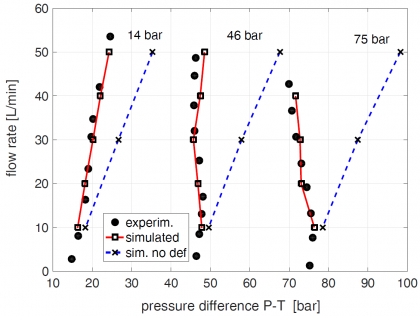 Figure 3
More analyses and details are available in:
ALTARE G, RUNDO M, OLIVETTI M, 2016: 3D Dynamic Simulation of a Flow Force Compensated ...
FINESSO R, RUNDO M, 2017: Numerical and experimental investigation on a conical poppet ...
RUNDO M, ALTARE G, 2017: Comparison of Analytical and Numerical Methods ...